- PRODUCTS
ApplicationFormatApplicationFormatApplicationFeatured


NEWS
News & Events
CFB750-300SXX-CMFD Series Parallel and Series Applications
07
May
May 7, 2021

Product Introduction:
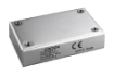
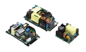
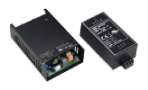
Cincon’s DC-DC Chassis-mount CFB750-300S-CMFD Series offers output voltages of 12V, 15V, 24V, 28V, 36V and 48V with 750W output power. This series contains the industry standard full-brick module with the input filter circuit. It comes with input voltage range from 200 to 450Vdc and reinforced 3000Vac isolation. This product meets EMC: EN55032 standard and is compliant to Fire & Smoke EN45545-2. Also, with high efficiency up to 90%, it works under the operating case temperature from -40°C to 80°C. While screwing on a metal plate or heat sink which improves the heat dissipation, this series could have a better performance on power derating curve. Additionally, the low no load power consumption (10mA) is an ideal solution for the power supply system. The standard control function has remote on/off (positive or negative) and goes with variable resistor to quickly adjust the output voltage. This product is equipped with fully protected functions, including Under-voltage Lockout (UVLO), Input Over Voltage Protection (Input OVP), Over Current Protection (OCP), Over-temperature Protection (OTP), and continuous short circuit protection. The CFB750-300SXX-CMFD Series is suitable for distributed power architectures, telecom, servers, base stations, battery operated equipment, and other industrial applications.
Preface:
As the demand for higher power DC-DC converters has been gradually increasing, system engineers may need to adopt DC power modules in parallel and in series use to increase the overall output power and output voltage because they have to consider simplifying the material list and controlling stock inventory and think about how to attain the goal of satisfying the system’s current, efficiency, and reliability. Cincon CFB750-300S CFMD can offer users several combinations in parallel and in series, which is an exceptional solution to the challenge of saving redesign time. This article will introduce how CFB750-300S24N-CFMD accomplishes the goal of the power converter in parallel use for current balance to raise the output current and in series use to increase output voltage.
CFB750-300S24N-CMFD in Parallel:
The optimal scenario of a parallel power system is that each power module provides current to each load stably and equally. There two types for each module in parallel connection to provide current eqaully─active and passive current-sharing. Because the output current of each power module is not the same in parallel connection, if power module does not have the current-sharing function to share the current evenly, it would cause the unbalanced current outputs to the load. The power module with higher load current will generate higher power output. This will reduce the life of the power module in the long run or result in power module overload, and thus it will cause output failure due to the trigger of over-temperature protection (OTP). In addition, when one module triggers OTP, sooner or later the other power modules in parallel connection will also be overloaded and start the OTP.
1.Passive current-sharing: The simple way to achieve current-sharing is voltage droop method (Figure 1). This way is to add an external resistor at the output of the power converter. It will, with the increase of the load current, make the output voltage decrease to reach to the current sharing balance between power modules. The output current difference among three power modules, when the external output resistance increases, will be minimized to achieve the current sharing. There is no need for signal communication or transmission among the modules because it is an open circuit to reach to the current sharing. Each power module is independent without any other extra control circuit. Nevertheless, the power modules with larger load currents will have more power consumption since the resistors would cause lower output efficiency. It is hard to reach to current-sharing among power modules with different power outputs. This is the biggest drawback of the voltage droop method.

(Figure 1)
2. Active current-sharing: This way is to take the current signal connected among power modules as references. Each power module will adjust the output voltage by comparing its output current signal with other signals of other modules to balance the output current. CFB750-300S CMFD employs the average current method to achieve current sharing by obtaining the current signals of all power modules. These signals are automatically averaged as the reference signal to each power module (Figure 2). The power converter with a lower output current will increase the output voltage to raise the output current while receiving the reference signal. Thus, the output current would reach to the average. The advantage of active current-sharing is that it does not require to add additional resistor, preventing the output efficiency from extra decrease. Each power module can achieve the load-current sharing by only adding a signal line connecting to each other.
As mentioned above, people may know that the better output efficiency gives “Active Current-Sharing” a big advantage over “Passive Current-Sharing”. Cincon offers a series of test data as follows.
CFB750-30024N-CMFD 3PCS in parallel test:
The table below is the specs. of DC-DC converters.
| DC to DC Converter | CFB750-300S24N-CMFD (750W) |
| Input voltage | 200V - 425Vdc, Nominal Inpuy 300Vdc |
| Output voltage | 24Vdc |
| Output current (full load) | 31.25A |
| Efficiency (typ.) | 89% |
The diagram of the CFB750-300S24N-CMFD 3PCS in parallel test is below.

(Figure 2)

(Parallel Connection)
The three DC-DC converters with the same specs. operate in parallel. With the same input source of 300Vdc, the power modules will stably output 24Vdc. The load current will be recorded by each increase of 25%. The data will demonstrate the output current of each power module and the overall output current.
| 25% of FULL LOAD | |
 (p5-1) (p5-1) |
|
| CH1: Io_tot (Io1+Io2+Io3) | CH2: Io1 |
| CH3: Io2 | CH4: Io3 |
| 50% of FULL LOAD | |
 (p5-2) (p5-2) |
|
| CH1: Io_tot (Io1+Io2+Io3) | CH2: Io1 |
| CH3: Io2 | CH4: Io3 |
| 75% of FULL LOAD | |
 (p6-1) (p6-1) |
|
| CH1: Io_tot (Io1+Io2+Io3) | CH2: Io1 |
| CH3: Io2 | CH4: Io3 |
| 100% FULL LOAD | |
 (p6-2) (p6-2) |
|
| CH1: Io_tot (Io1+Io2+Io3) | CH2: Io1 |
| CH3: Io2 | CH4: Io3 |
In general applications, dynamic load should be considered. When the load current changes in a split second, we should examine whether the output current is influenced by the change. The pictures below are the dynamic response of the output current of the three power modules. The current waveforms show the changes of 25% and 50%. It can be seen from the pictures below that the output current of the system remains stable when the load varies.
| 50%~100% FULL LOAD | |
 (p7-1) (p7-1) |
|
| CH1: Io_tot (Io1+Io2+Io3) | CH2: Io1 |
| CH3: Io2 | CH4: Io3 |
| 100%~50% FULL LOAD | |
 (p7-2) (p7-2) |
|
| CH1: Io_tot (Io1+Io2+Io3) | CH2: Io1 |
| CH3: Io2 | CH4: Io3 |
| 75%~100% FULL LOAD | |
 (p8-1) (p8-1) |
|
| CH1: Io_tot (Io1+Io2+Io3) | CH2: Io1 |
| CH3: Io2 | CH4: Io3 |
| 100%~75% FULL LOAD | |
 (p8-2) (p8-2) |
|
| CH1: Io_tot (Io1+Io2+Io3) | CH2: Io1 |
| CH3: Io2 | CH4: Io3 |
| The efficiency curve of 3Pcs CFB750-300S24N-CMFD in Parallel at 300Vdc input | |||||||||||||||||||||||||||||||||||||||||||||||||
|
 |
||||||||||||||||||||||||||||||||||||||||||||||||
The table and chart above show that when the 3Pcs of CFB750-300S24N-CMFD operate in parallel at 2250W output, its efficiency remains up to 90%. The load current sharing of each power module is stable and equal without being overloaded.
CFB750-300S24N-CMFD in Series:
CFB750-300S24N-CMFD 3PCS in Series Test:
The diagram of the 3PCS CFB750-300S24N-CMFD in series test is below.

(Figure 3)

(Series Connection)
The three DC-DC converters with the same specs. operate in series. With the same input source of 300Vdc, connecting every power module with 24Vdc output will have stable output 72Vdc. The load current will be recorded under 50% and 100%. The data will demonstrate the output and the total output current of each power module.
| 50% of FULL LOAD | |
 (p10-1) (p10-1) |
|
| CH1: Io_tot (Total Io Current) | CH2: Vout_tot (Vout1+Vout2+Vout3) |
| CH3: Vout 2 + Vout 3 | CH4: Vout 3 |
| 100% FULL LOAD | |
 (p11-1) (p11-1) |
|
| CH1: Io_tot (Total Io Current) | CH2: Vout_tot (Vout1+Vout2+Vout3) |
| CH3: Vout 2 + Vout 3 | CH4: Vout 3 |
The pictures below are the dynamic response of the output current of the three power modules. The current waveforms show the changes of 25% and 50%. It can be seen from the pictures below that the output voltage and current of the system remain stable when the load varies.
| 50-100% FULL LOAD | |
 (p11-2) (p11-2) |
|
| CH1: Io_tot (Total Io Current) | CH2: Vout_tot (Vout1+Vout2+Vout3) |
| CH3: Vout 2 + Vout 3 | CH4: Vout 3 |
| 100-50% FULL LOAD | |
 (p12-1) (p12-1) |
|
| CH1: Io_tot (Total Io Current) | CH2: Vout_tot (Vout1+Vout2+Vout3) |
| CH3: Vout 2 + Vout 3 | CH4: Vout 3 |
| 75-100% FULL LOAD | |
 (p12-2) (p12-2) |
|
| CH1: Io_tot (Total Io Current) | CH2: Vout_tot (Vout1+Vout2+Vout3) |
| CH3: Vout 2 + Vout 3 | CH4: Vout 3 |
| 100-75% FULL LOAD | |
 (p13-1) (p13-1) |
|
| CH1: Io_tot (Total Io Current) | CH2: Vout_tot (Vout1+Vout2+Vout3) |
| CH3: Vout 2 + Vout 3 | CH4: Vout 3 |
The pictures below are the waveforms under 50% and 100% load of the three power modules during starting up. It can be seen from the pictures below that the output voltage and current of the system remain stable when each power module starts up.
| 50% of FULL LOAD | |
 (p14-1) (p14-1) |
|
| CH1: Io_tot (Total Io Current) | CH2: Vout_tot (Vout1+Vout2+Vout3) |
| CH3: Vout 2 + Vout 3 | CH4: Vout 3 |
| 100% FULL LOAD | |
 (p14-2) (p14-2) |
|
| CH1: Io_tot (Total Io Current) | CH2: Vout_tot (Vout1+Vout2+Vout3) |
| CH3: Vout 2 + Vout 3 | CH4: Vout 3 |
| The efficiency curve of 3Pcs CFB750-300S24N-CMFD in Series at 300Vdc input | |||||||||||||||||||||||||||||||||||||||||||||||||
|
 |
||||||||||||||||||||||||||||||||||||||||||||||||
The table and diagram above show that when the 3PCS CFB750-30024N-CMFD operate in series at 2250W output, its efficiency remains up to 90%, indicating that each power module is under load balance without being overloaded.
Notice:
To fulfill greater accuracy of the current sharing for each power module, it is recommended completing the following items on the front-end converter and the wiring plan.
It is suggested that all modules in series or parallel connection should share the same input source to ensure the input voltage of each power module is the same, and the startup time difference can also be minimized. Different input sources may cause the output failure because different startup time may make the module with faster startup time be overloaded and trigger the protection. The interference (EMI) issue may also occur by using different input sources.
The current path through wire and PCB cooper would lead to current error; thus, the users need to pay more attention on length of the wiring. It would be better to let the path be symmetrical for every power module in series or parallel.
The output voltage in parallel should be as equal as possible to prevent the large difference, leading to the current-sharing to be unbalanced.
The current sharing tolerance should be from -10% to +10%. It is recommended that each power module in parallel should be considered that the maximum of consuming output power is 90% of full load. This can prevent one of the power modules from output failure because of the instantaneous overload current which triggers the protection.
The output current in series requires Shunt Diode. When a single power module is being protected, Shunt Diode can be as an alternative path of the current in order to prevent the current flowing into the module which would cause the component damage inside the module or abnormal operation.
Conclusion:
This article demonstrates how to use Cincon’s CFB750-30024N-CMFD in parallel and in series as the example to increase the overall output power and output voltage. The results show the practicality of parallel and series connection. As the waveform shown, each power module in parallel shows current sharing, and each power module in series is under load balance. Additionally, the overall output voltage and current under dynamic load conditions remains stable with great efficiency of 90%. Cincon’s CFB750-300SXX-CMFD Series truly offers users a saving-time power solution when higher output power and voltage are required.
Check the products now:CFB750-300SXX-CMFD Product Page