- PRODUCTS
ApplicationFormatApplicationFormatApplicationFeatured


NEWS

News & Events
The advantage and application of the BUS pin of CHB200W12 & CHB150W12 Series
22
Apr
Apr 22, 2022

Electronic devices lay stress on the reliability and stability of power conversion products in various applications such as industrial, automation, railway, telecom, IPC, medical, etc. In these applications, many electronic devices contain MCU/CPU. In addition, the holdup time for the moment after the interruption of power supply is critical. The holdup time is defined as the duration of time that the DC-DC converter output will remain active following a loss of input power. System designers would require the holdup time feature based on the device characteristics and product regulations in these applications.
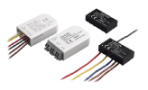
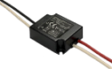
Cincon also provides the feature for the holdup time. Today Cincon is introducing the feature of the BUS pin of CHB200W12 series and CHB150W12 series as the reference. The BUS pin is here for increasing the holdup time with external circuitry. The CHB200W12 and CHB150W12 series are very popular and widely used in the railway applications. The BUS pin feature could offer the convenience for the system designer to keep or increase the holdup time.
Before moving on to the details, let’s firstly introduce the formula for calculating the value of Hold up Bus Cap. This formula could be applied to solving the holdup time puzzle.

According to the formula, when the input voltage increases and the Vturnoff is lower, the holdup time would extend and the capacitance would be lower. On the other hand, when the input watt and holdup time are larger, the capacitance would be higher.
Let’s take CHB200W12 and CHB150W12 series for example:

Fig1. BUS pin
Fig2. Input voltage & BUS voltage curve
When we look at the red line in the graph above, the BUS voltage keeps stably at 73Vdc when the input voltage rises from 14V to 73V. When the input voltage is above 73V, then BUS voltage goes up correspondingly. In addition, when we see the section in blue from the graph, the input voltage drops to 70Vdc and the BUS voltage remains 73Vdc until the input voltage falls below the UVLO. Therefore, the BUS pin feature could decrease the need for capacitance based on the formula, leading to the lower inrush current and the smaller size of capacitor which are great advantages for system designers. These advantages would show up at the input voltage in the 14Vdc-73Vdc range.
In this section, we are comparing the difference of capacitance between having the BUS pin and NOT having the BUS pin feature. Let’s take CHB200W12 series as the example.
After the calculation according to the previous formula, we could see result below:

It’s obvious to find out that it requires larger capacitance for a normal DC-DC converter when the input voltage lower. In addition, the capacitance is even greater when the holdup time is longer. However, for CHB200W12 series, it ONLY needs the relatively smaller amount of capacitance to reach to the desired holdup time due to the help of BUS pin feature. In this case, it has lower inrush current and uses the smaller size of capacitor.
For the general use of CHB200W12 and CHB150W12 series without the holdup time feature, they only need to add a 240uF(C4) capacitor to connect with the BUS pin in order to let the DC-DC converter work stably while the input voltage is in the 14Vdc-73Vdc range. See the general test setup information below:

C2: 1uF/1210 ceramic capacitor
C3: 10uF tantalum capacitor
(10uF aluminum capacitor for 48Vout).
C4: 240uF (VISHAY 118 AHT series)
When the holdup time is required, it only needs to add a capacitor(C5). See the setup below:

C4: 240uF (VISHAY 118 AHT series)
D1: 200V/10A
R1: 3mΩ/1W


Fig6.
The CHB200W12 and CHB150W12 have the built-in protection design for the BUS pin to prevent inverse current while the input short circuit occurs. For those DC-DC converters without the built-in protection, system engineers need to add extra circuit and components. In addition, Cincon also provides the reference design for limiting the inrush current which is caused by the added capacitance for holdup time. See the design below:

Fig7.
For the holdup time requirement, here’s the example in the standard of the railway application. In the EN 50155 power supply test, the interruptions of voltage supply and the supply change-over are categorized into the following different classes:
Interruptions of voltage supply:
Class S1: No voltage interruption. No performance criterion is requested but the equipment shall continue to operate as specified after the voltage interruption.
Class S2: Interruption time 10ms. performance criterion A
Class S3: Interruption time 20ms. performance criterion A
Supply change-over:
Class C1: At 0.6*Vin during 100ms (without interruptions). Performance criterion A
Class C2: During a supply break of 30ms stating at Vin. Performance criterion B
For meeting the EN 50155 test requirements, The following are the test results of holdup time of CHB200W12 series under the input open circuit and short circuit conditions:
The waveforms of open circuit test:

Fig8.
Hold up time for 10ms
Vin: 24V, Bus Cap: 2400uF, Output Max Load

Fig9)
CH1:Vin, CH2:Vout, Maximum Load
Hold time: 14.9ms.
Vin: 36V, Bus Cap: 2400uF, Output Max Load

(Fig10)
CH1:Vin, CH2:Vout, Maximum Load
Hold time: 15.0ms.
Vin: 48V, Bus Cap: 2400uF, Output Max Load

(Fig11)
CH1:Vin, CH2:Vout, Maximum Load
Hold time: 15.2ms.
Vin: 72V, Bus Cap: 2400uF, Output Max Load

(Fig12)
CH1:Vin, CH2:Vout, Maximum Load
Hold time: 16.8ms.
Hold up time for 30ms
Vin: 24V, Bus Cap: 7200uF, Output Max Load

(Fig13)
CH1:Vin, CH2:Vout, Maximum Load
Hold time: 39.1ms.
Vin: 36V, Bus Cap: 7200uF, Output Max Load

(Fig14)
CH1:Vin, CH2:Vout, Maximum Load
Hold time: 39.3ms.
Vin: 48V, Bus Cap: 7200uF, Output Max Load

(Fig15)
CH1:Vin, CH2:Vout, Maximum Load
Hold time: 41.4ms.
Vin: 72V, Bus Cap: 7200uF, Output Max Load

(Fig16)
CH1:Vin, CH2:Vout, Maximum Load
Hold time: 43.0ms.
The waveforms of short circuit test:

Fig17.
Hold up time for 10ms
Vin: 24V, Bus Cap: 2400uF, Output Max Load

(Fig18)
CH1:Vin, CH2:Vout, Maximum Load
Hold time: 14.85ms.
Vin: 36V, Bus Cap: 2400uF, Output Max Load

(Fig19)
CH1:Vin, CH2:Vout, Maximum Load
Hold time: 15ms.
Vin: 48V, Bus Cap: 2400uF, Output Max Load

(Fig20)
CH1:Vin, CH2:Vout, Maximum Load
Hold time: 14.9ms.
Vin: 72V, Bus Cap: 2400uF, Output Max Load

(Fig21)
CH1:Vin, CH2:Vout, Maximum Load
Hold time: 16.45ms.
Hold up time for 30ms
Vin: 24V, Bus Cap: 7200uF, Output Max Load

(Fig22)
CH1:Vin, CH2:Vout, Maximum Load
Hold time: 38.6ms.
Vin: 36V, Bus Cap: 7200uF, Output Max Load

(Fig23)
CH1:Vin, CH2:Vout, Maximum Load
Hold time: 36.1ms.
Vin: 48V, Bus Cap: 7200uF, Output Max Load

(Fig24)
CH1:Vin, CH2:Vout, Maximum Load
Hold time: 39.7ms.
Vin: 72V, Bus Cap: 7200uF, Output Max Load

(Fig25)
CH1:Vin, CH2:Vout, Maximum Load
Hold time: 40.2ms.
According to waveforms from the test result, when the short circuit occurs, it will not cause short circuit of the capacitor connected to the BUS pin. In addition, with the help of BUS pin, it also reduces the risk of inrush current, prevents the inverse current and offers the stable holdup time.
Conclusion:
Cincon is experienced and sophisticated in railway power solution. We have helped customers for the power solutions in many railway applications such as power distribution system, lighting, brake system, door control system, and windshield wiper, etc. With the BUS pin of CHB200W12 and CHB150W12 series, it is able to offer stable holdup time operation. Moreover, it also lowers inrush current, reduces the size of capacitor and saves the space in the end user devices for the system designers.
Product Page: CHB200W12 & CHB150W12
For more support, contact us: sales@cincon.com.tw