- PRODUCTS
ApplicationFormatApplicationFormatApplicationFeatured


NEWS

News & Events
How to select a railway DC-DC converter
21
Jun
June 24, 2022

Introduction:
The railway system could be traced back to the early 19th century and developed into various modern models nowadays. The power source came from AC distribution line through Over-head wire system (AC), or Third-rail system (AC or DC) into the cabinet and power most of electrical blocks with DC power. Due to the fluctuation or disturbance of power distribution line, the requirements of power converter have to meet certain criteria especially EN 50155 standard. In this article, we will discuss the key factors and the concepts to choose a right DC-DC power converter for your system.

Fig 1. Power distribution on Railway
Key Factors for considering Railway DC-DC converter
To sustain the fluctuated power line and operate under harsh environment on railway system, the DC-DC converter has to consider the following key factors:
1.Input voltage range
The distributed voltages in a railway DC system include 24V, 28V, 36V, 48V, 72V, 96V, and 110V. To cover the transient condition, the voltage range has to include from 0.6 to 1.4 times of the nominal voltage. A railway system would likely have 24V & 110V as the distributed voltages, meaning the voltage range would across from 14.4V to 154V. In that case, a 12:1 input range DC-DC converter would cover all.
| Nominal input voltage (Vin) | Min (0.6 * Vin) | Max (1.4* Vin) |
| 24V | 14.4V | 33.6V |
| 28V | 16.8V | 39.2V |
| 36V | 21.6V | 50.4V |
| 48V | 28.8V | 67.2V |
| 72V | 43.2V | 100.8V |
| 96V | 57.6V | 134.4V |
| 110V | 66V | 154V |
2.RIA12 standard for UK
RIA12 is a much stricter standard for input surge requirements, which requests to stand 3.5 times of input voltage for 20ms. The function is achieved by external circuitry with MOSFET switches and controlling IC, which sense the input voltage for protection.
3.Operating temperature
In the EN 50155 standard, there are 6 different Classes from OT1 to OT6. They are defined by various applied scenarios. See the following:
| Class | Operating temperature (°C) | Application scenario |
| OT1 | -25 to +55 | Passenger and Pilot cabinet |
| OT2 | -40 to +55 | Passenger and Pilot cabinet |
| OT3 | -25 to +70 | Inside the electronic equipment |
| OT4 | -40 to +70 | Inside the electronic equipment |
| OT5 | -25 to +85 | Inside Internal combustion engine |
| OT6 | -40 to +85 | Inside Internal combustion engine |
4.Hold-up time for interruption
The hold-up time is to ensure that the system stays stable even the input source is cut off (0V) for a short period of time. The first table indicates the requirements of the three classes in EN 50155 for the interruption of input voltage supply.
| Class | Description |
| S1 | No need to meet any criteria. The unit should work functionally after power resume back. |
| S2 | Need to meet 10ms hold-up time when Vin drop to 0V. |
| S3 | Need to meet 20ms hold-up time when Vin drop to 0V. |
The second table shows the requirements of two classes for output voltage variation during power supply change-over.
Supply change-over:
| Class | Description |
| C1 | Need to meet 100ms hold-up time when Vin drop to 0.6 times of nominal voltage |
| C2 | Need to meet 30ms hold -up time when Vin drop to 0V. |
5.EMC (Electromagnetic compatibility) consideration
EMC could be separated into EMI(Interference) and EMS(Susceptibility). EMI has to follow EN 50121-3-2 standards and EMS needs to meet IEC 61000-4 mostly.
The table below shows the critical test items:
| Test Item | Criterion | Test Condition (Example) |
| ESD | IEC 61000-4-2 | Level 3: Air ±8kV, Contact ±6Kv |
| Radiated Immunity | IEC 61000-4-3 | Level 3: 80~1000Mhz, 20V/m |
| Fast Transient | IEC 61000-4-4 | Level 3: On power input port, ±2kV (EN50155) Level 4: On power input port, ±4kV (EN55035) |
| Surge | IEC 61000-4-5 | Level 4: Line to earth, ±4kV, Line to line, ±2kV (EN50155) Level 3: Line to earth, ±2kV, Line to line, ±1kV (EN55035) Level 4: Line to earth, ±4kV, Line to line, ±2kV, with external input capacitor 120uF/220V KXJ series (EN55035) |
| Conducted Immunity | IEC 61000-4-6 | Level 3: 0.15~80MHz, 10V |
6.Reliability testing
In order to accommodate railway environment, multiple reliability and environment tests are required. The following table shows the common requirements.
| Test item | EN 50155 Reference Clause | Reference Standard |
| Low-Temperature Start-up test | 13.4.4 | EN 60068-2-1 |
| Dry Heat Test | 13.4.5 | EN 60068-2-2 |
| Low-Temperature storage test | 13.4.6 | EN 60068-2-1 |
| Cycle Damp test | 13.4.7 | EN 60068-2-30 |
| Random vibration Heat test | 13.4.11 | EN 61373 |
| Simulated Long Life Test at Increased Random Vibration Levels | 13.4.11 | EN 61373 |
| Shock Test | 13.4.11 | EN 61373 |
| Fire & Smoke | - | EN 45545-2 |
How to select a railway DC/DC converter for your system
In order to choose the right DC-DC converter for railway applications, the following are the common applications on the railway system. (Fig2)

Fig 2. Common applications
1.Cockpit (Pilot cabin):
a.Central computer system
b.Electronic monitor display
c.Information system
d.Broadcast system
2.Passenger cabin:
a.Electronics monitor display
b.Cabin door control
c.Alert system
d.HVAC system
3.Propulsion system:
a.Traction control system
b.Sensor control system
4.Rail track system:
a.Signal control system
b.Safety system
c.Crossing system
Depending on the application, the DC-DC converter would be working under different environments where the operating temperature, shock & vibration, and humidity etc. are differently regulated for testing in order to ensure the safety and reliability.
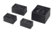
Another point to consider is how to install the DC power in the system. It could be mounted on the system’s PCB board, mounted inside the system chassis, or hooked on the din-rail.

Four quick steps to choose the railway DC-DC converter you need:
First is to confirm the right input range of your system needs. The railway system could switch among 24V, 28V, 36V, 48V, 72V, 96V, and 110V. Ensure the Vin range that covers the bottom and upper voltage needs.
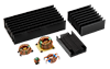
Second, choose the needed output voltage, wattage, and calculate the power derating based on the operating temperature. The heat could be dissipated by standard-size heatsink or system baseplate.
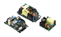
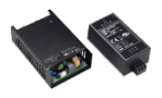
Third, based on where to apply the DC-DC converter, consider the installation type of the DC-DC converter. If it is built into the system board together, the external circuitry for EMI noise filtering and hold-up time capacitors are needed. On the other hand, chassis mount or din-rail solutions could be installed independently without the external circuitry because the filtering circuitry is already built in, and it dramatically saves the development time which may be caused by EMI issue.
Fourth, check the product datasheet for the needs of operating temperature, Insulation requirement, Shock& Vibration, EMC, Immunity test, fire & smoke test etc. These requirements are based on the EN 50155 mostly.
Lastly, evaluate the system performance with the DC-DC converter and make sure the requirements of EN 50155 are met.
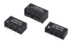
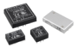
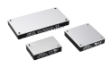
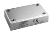
Cincon power solution for railway application:
Cincon has a wide variety of DC-DC converter series that meet the EN 50155 standards. These series are from 18:1 to 2:1 input range and the power range starts from 8W to 600W. Besides, the chassis mount modules with built-in filter for EMI solution (CMFC/D) are available. In addition, EMI filter for each series, and railway turn-key solution (ECRT/EDRT) are offering now. More importantly, Cincon has a strong R&D team for technical supports.
For details of product information, please refer to the Railway Solution.
Contact sales@cincon.com.tw for support.