- PRODUCTS
ApplicationFormatApplicationFormatApplicationFeatured


NEWS


News & Events
The Ground Rules to Select and Build a Modular DC-DC Power System-III
10
Dec
Dec 10, 2021

Part III—Safety consideration
Introduction:
In the previous articles, we discussed fundamental concepts and EMI consideration for building DC-DC modular system. In rare cases, the abnormal peak current flows in the modular system, which is at risk of damaging the whole power system. To avoid catastrophic situation, safety circuitry design for protecting the power system is quite important. In this article, we will discuss key points to select right Fuse and TVS (Transient Voltage Suppressor) for building front-end safety protection circuitry.
Main function of fuse and selection:
There is a small piece of metal wire in the electrical fuse that protects the system by melting itself down. In a DC-DC modular system circuitry, it is placed at the front-end to protect the whole system. Ideally, when the disastrous situation happens, the fuse acts as a protection to let the circuitry to be “open” before the tremendous energy flows into the back-end components and damages the whole system. On the other hand, overprotective design would cause troubles, which sacrifices the fuse easily. Therefore, selecting a suitable rating fuse for DC-DC modular system is critical. The following are the factors for selecting a suitable fuse:
a. Choosing a certified fuse
To avoid safety recognition issues, we recommend choosing the products certified in both America and Europe. Most fuses are certified to be used in the AC side. It would be a plus to select a fuse which is also certified to be used in the DC side.

Fig.1 Safety standard
b. Fuse types
Fuse could be simply categorized in two types: fast-acting and time-delay. Generally, the fast-acting type could act instantly once the current flowing into the system exceeds the current rating of the fuse. The time-delay type is able to hold a short period of time before breaking down. Normally, the selecting standard depends on the inrush current of the DC-DC modular system. The time-delay type would be suitable for high inrush current system, and the fast-acting type is used for the low inrush current system.
c. Current rating
The continuous operating current should always be under the maximum current rating of the fuse. It suggests taking an extra 10~25% margin based on the requirement. The maximum continuous operating current could be roughly calculated at the low line input voltage in a full-load condition. Also, the efficiency factor needs to be considered.
d. Voltage rating
In a DC-DC modular system, the operating voltage should always be under the maximum voltage rating of the fuse. This is important since fuse is not sensitive to the change of voltage.
e. Melting integral (Nominal melting)
A fuse is opened when the thermal energy accumulates to its upper limit, and it will break down itself. The equation I² t, which indicates Current and Time are two key factors, can calculate the nominal melting rating. Beware various types of inrush current waveform affect the I² t equation because of the energy difference.
The following is an example of average current curve (I-T curve), which helps designers to find out the ideal current rating fuse and its melting condition. It could be seen from three aspects.
1. If we select a 0.315A current rating fuse running under 1A condition, it could last within 1.8 secs and the fuse would be opened.
2. If we select a 0.315A current rating fuse and want to know the minimum running current which opens the fuse within 0.1 sec, it shows around 2.9 A.
3. If we want to select a current rating fuse which could be opened within 1 sec at 10A, a 2.5A current rating is the closest one meeting this requirement.

Fig.2 I-T curve example (Reference from Betterfuse 932 series)
f. Breaking capacity
The breaking capacity could also be described as interrupted current rating, which indicates the maximum fault current to break the fuse. This parameter is used for defining the maximum current during fault testing such as short circuitry or overload testing to ensure that the fuse does not break down easily.

Fig. 3 IEC 60127 standard for Fuse breaking capacity
g. Operating temperature and derating curve
Since the mechanism of fuse is based on thermal energy, the operating temperature would affect the current rating significantly. Check the temperature derating curve in the specification while calculating the current rating.

Fig. 4 Temperature derating curve example (Reference from Betterfuse 932 series)
Transient voltage suppression:
Besides the peak current protection for a DC-DC modular system, the transient high voltage such as spike or surge would also damage the components in the power modular system. TVS (Transient Voltage Suppressor) diode is commonly used at the front end to protect the whole power system. The key parameters for selecting suitable TVS are as follows:
a. Reverse standoff voltage (VR)
The reverse standoff voltage (VR) describes the voltage of TVS that could hold before reversing. The working voltage range should be within this volume.
b. Breakdown voltage and clamping voltage
The breakdown voltage is the maximum voltage that breaks through the TVS, and clamping voltage describes the voltage while peak current goes through. Both parameters should be considered as an upper limit line to protect the power system.
c. Peak pulse current
The peak pulse current describes the maximum current TVS could hold. Beware the peak pulse current should not exceed this rating since TVS isn’t for overcurrent protection purpose.

Fig. 5 TVS diode IV characteristic curve
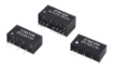
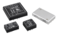
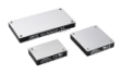
Module in application: CHB200W12
In Cincon’s application note, we have the recommendation of Fuse and TVS rating for the system application. Taking CHB200W12 as an example:

Fig.6 CHB200W12 suggestion circuitry
CHB200W12 is a 200W DC-DC converter with 90% efficiency and the 14 ~160Vdc input range. Let’s roughly calculate the maximum input current first:
200 / 14/ 0.9 ≈ 15.87A
Then we need to consider the thermal derating, assuming 10% current derating under 40℃ operation, and 25% margin to meet safety standard (UL as an example).
15.87 /0.9/0.75 ≈ 23.5A
In the application note, we recommend using a 25A rating fuse. Also, the specification indicates the inrush current maximum 0.1 (A² s), which could be cross checked from the selected fuse specification to see if it exceeds the rating.
TVS and Cin should be added if the system needs to meet EN 61000-4-4 and EN 61000-4-5.
Check the CHB200W12 Specification and Application note for more details.
Conclusion
The safety protection for circuitry plays an important role in protecting the whole power system. Key parameters in Fuse and TVS were discussed for selecting suitable components. There are some cases or applications that additional front-end protection circuitry design is needed. Contact us for more support and inquiries!
Check more:
Build a Modular DC/DC Power System
Build a Modular DC/DC Power System-II
Contact for more support: sales@cincon.com.tw