- PRODUCTS
ApplicationFormatApplicationFormatApplicationFeatured


NEWS

News & Events
The Ground Rules to Select and Build a Modular DC/DC Power System-II
12
Nov
Nov 12, 2021

Part II—EMI filter design
Introduction:
Last time, we discussed the fundamental concept to build a DC/DC modular system (Part I) and the overall picture in system application. Today we are focusing on noise. Noise reduction has been mentioned regularly and troubled engineers while implementing the power module into the system. In this article, we are mainly targeting at the input filter design and EMI noise reduction solutions.
1. Where are noises from and the impacts?
The biggest advantage of switching mode power supply is the high efficiency and compact size while compared to the efficiency of typical linear type. However, with the high frequency switching mechanism, severe noises are generated and cause EMC/EMI (Electromagnetic Compliance/Interference) issues if we are not handling well. In general, two types of noise could be summarized: Conducted Noise and Radiated Noise.
Conducted noise—Common mode & Differential mode:
Conducted noise could be discussed and analyzed from two aspects: common mode and differential mode. The common mode noise exists between Positive/Negative line to Ground due to the voltage at switching node coupled with parasitic capacitance which exists in the transformer (between the primary and the secondary side) and the outer case to reference ground; the differential mode noise, on the other hand, exists between Positive and Negative line due to the current fast alternating at the switch node, generating the unwanted voltage which is in the form of noise. Luckily, the differential mode noise travels within Positive and Negative line only, but the common mode noise would travel through ground which causes problems to the system. Generally, we measured Positive and Negative line for conducted noise from 0 to 30M Hz to identify if it is in compliance with EMI standards.

Fig.1 Conducted noise loop
Radiated noise:
As the word “Radiated” means, the radiated noise is wirelessly transmitted through air by radiating from the unit itself. It is mostly caused by attenuation through signal transmitting and happens on cable or connectors. We measure this high frequency noise from 30M up to 1G Hz to identify if it is in compliance with EMI standards.

Fig.2 EN55022/55032 EMI standard (Conducted)

Fig.3 CISPR 22/32 EMI standard (Radiated)
In order to reduce the interference of these noises in the PSU, engineers have come out with LC combination filter to bypass or block the noise. The concept and methodology are discussed next.
2. Noise reduction solution: Filter design concept and topology
For conducted noise, both CM (Common Mode) and DM (Differential Mode) noises are generated due to fast switching and alternating voltage or current. The combination of inductor and capacitor (LC filter) could effectively mitigate the noise disturbing the transmission line. Explanation as following:
Common mode noise solution:
In the common mode noise solution, the common mode choke and Y cap are two key components. Common mode choke consists of two inductors with the same polarity routing on a core. The Y cap is defined as the capacitor from Positive or Negative line connects to ground. The path from Positive line to ground or Negative line to ground could be seen as a low-pass filter, which mitigates the high frequency noise between Positive and Negative line to case ground.

Fig.4 Common mode noise solution
Differential mode noise solution:
In the differential mode noise solution, the combination of the differential mode choke and two capacitors, known as the Pi filter, is commonly used. The differential mode choke could be simply an inductor, and the two capacitors are connected between Positive and Negative line. This combination could be regarded as a low-pass filter, which lessens the noise flowing between the Positive and Negative line.

Fig.5 Differential mode noise solution
Radiated noise solution:
Radiated noise could be seen as the emitting noise signal from a component like an antenna, and the straightforward solution is to block the radiative source by shielding. Another suggestion is when doing layout works, try to keep current loop as short as possible to avoid coupling with inductance on the PCB traces.

Fig.6 Radiated noise consideration
3. Modules in application: CHB200W12 & CHB300W
The following are two examples of DC/DC converter with external reference circuitry to meet the EMI standard.
CHB200W12 EMC consideration—Conducted and Radiated Emission:

Fig.7 CHB200W12 EMC reference circuitr
At the input stage, L101 and L102 are two-stage of common mode choke, and CY1 to CY8 are Y caps. These components mainly deal with common mode noise; for C101 to C105, these capacitors are connected between the positive and the negative line to lessen the differential mode noise. Since the differential mode choke is located at the front-end of module, no need to add it into the external circuitry. At the output stage, the capacitors are paralleled to reduce ripple noise and L102 choke is to reduce Radiated noise from the connector side.
CHB300W EMC consideration—Conducted Class A:

Fig.8 CHB300W EMC reference circuitry
At the input stage, the Pi filter consists of two capacitors (C1 & C2) and the differential mode choke (L1) to deal with differential mode noise. The L2 common mode choke is mainly to handle common mode noise. Since the Y caps are included inside the module, no need to add them into the external circuitry.
See the details of EMI testing results as the references:
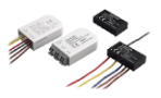
4. Cincon’s DC-DC filter module—FM series
To save the development time of using a DCDC converter module, Cincon has series of filter module to fit input and output stage. These are input filter modules, FM05D, FM10D & FM10/20, and the output filter module FM30R, which have been verified to meet Railway application EN 50155 or ITE application EN 55032. If we look into the design methodology of these modules, they were the combination of inductors and capacitors as we discussed. Users could refer to the datasheet and application note for finding compatible DC/DC converter models and insertion loss waveform of CM & DM. For more information on the models and application, please checked earlier newsletter— Cincon EMI Filter Module.
Conclusion:
The EMI noise issue could be various based on the circuitry design inside the DC/DC converter and the PCB layout on the system board. The concept and solution to deal with the Conducted and Radiative noise are shown with two examples of the circuitry for CHB200W12 and CHB300W. The filter module is a compact and quick EMI solution for users to implement DC/DC converter module into system easier. Cincon has the strong and sophisticated R&D team and the chamber for EMI simulation to support customers, fulfill their needs and shorten the development time.
Related articles:
Build a Modular DC/DC Power System
Build a Modular DC/DC Power System-III
Contact for more support: sales@cincon.com.tw