- PRODUCTS
ApplicationFormatApplicationFormatApplicationFeatured


NEWS

News & Events
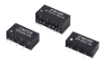
CHB200W12-72S for Railway Solution
07
Jan
Jan 07, 2022

Introduction:
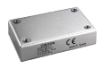
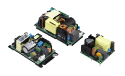
With many years of professional experience, Cincon Electronics has launched many power converters that help our business partners to solve the challenges of power supply applications. This article will introduce Cincon’s latest ultra-wide input DC-DC converter: CHB200W12-72S. This series is suitable for various applications because of the wide input voltage range. The CHB200W12-72S offers 200 Watts with a single output voltage of 12, 15, 24, or 48 VDC. The output voltage trimmed range is from -20% to +15%. In addition to being compliant to EN 50155 and EN 45545-2 railway standards, this DC-DC converter has the ultra-wide input range from 14 VDC to 160 VDC, along with 3000 VAC isolation voltage. Also, the operating altitude is up to 5000m, and the 90% efficiency is able to reduce the amount of energy loss. Inherited from Cincon’s power supply features and benefits, it has full protections of UVLO, Input OVP, OCP, OVP, OTP, and continuous short circuit protection, which ensures the stability of the end-device use.
Application:
We provide system designers with the CHB200W12-72S circuit diagram as reference which includes Input Filter, Output Filter, and Shunt Diode, and TVS. The circuit modular application is compliant to EN 50155 and EN50121-3-2 railway EMC standards. Referring to the circuit diagram can help system designers reduce the development time. The following are the circuit diagram, component information, and test results for railway solutions. Users can refer to the application notes to find the detailed data.
CHB200W12-72S Peripheral Circuit for Railway Turnkey Solution:
EN 55032 Class A conducted & radiated emission

Fig. 1 Circuit diagram


Fig. 2 PCBA
| Model Number | CHB200W12-72S12 | |
| Position | Spec. | Note |
| C101, C102, C105 | 1uF/250V SMD | 1812 X7R ceramic |
| C103, C113 | 220uF/200V, Aluminum cap. KXJ series | NIPPON CHEMI-CON KXJ series aluminum capacitor or equivalent |
| C106 | 68uF/200V, Aluminum cap.CS series | Nichicon CS series aluminum capacitor or equivalent |
| C114 | 120uF/220V, Aluminum cap. KXJ series | NIPPON CHEMI-CON KXJ series aluminum capacitor or equivalent |
| C201, C202 | 0.1uF/100V SMD | 0805 X7R ceramic |
| C203, C204 | 6.8uF/50V SMD | 1812 X7R ceramic |
| C205, C206, C207 | 10uF/50V SMD | 1210 X7R ceramic |
| C208 | 0.1uF/100V SMD | 1210 X7R ceramic |
| C209, C210 | 1uF/100V SMD | 1210 X7R ceramic |
| C211, C212 | 6.8uF/50V SMD | 1812 X7R ceramic |
| CY10 | 220pF/Y1 | TDK Y1 capacitor or equivalent |
| CY1 | 100pF/Y1 | TDK Y1 capacitor or equivalent |
| CY2 | 220pF/Y1 | TDK Y1 capacitor or equivalent |
| CY3, CY4 | 2200pF/Y1 | TDK Y1 capacitor or equivalent |
| CY5, CY6 | 2200pF/Y1 | TDK Y1 capacitor or equivalent |
| CY7, CY8 | 0.022uF/275Vac 10mm X2 | CARLI MPX Series X2 capacitor or equivalent |
| L101, L102 | 0.72mH 0.8mm*2/10T R-22/14/8B | MA100-C ALWIN or equivalent. |
| L201 | 0.12mH 0.7mm*8/2T | FCN0179C WELL LIGHT or equivalent. |
| D101 | SMCJ180A, | LITTELFUSE or equivalent |
| D102, D103 | STTH8R03DJF-TR | ST or equivalent |
| BEAD CORE | Add on CY5, CY6 | BRI 4*1.5*2 CHILISIN or equivalent |
Suggested PCB layout:

Fig. 3 PCB layout top view

Fig. 4 PCB layout bottom view
CHB200W12-72S EN50155 EMI Test Result:
Setup:

Fig. 5 Test set up
Input conduction:
| Line | Neutral |
 |
 |
EN50121-3-2 output conduction:
| Positive | Negative |
 |
 |
Radiation test result:
| Horizontal | Vertical |
 |
 |
CHB200W12 Peripheral Circuit for EN55032 Class B conduction & radiation emission:

Fig. 6 Circuit diagram


Fig. 7 PCBA
Component value:
| Model Number | CHB200W12-72S24 | |
| Position | Spec. | Note |
| C101, C102, C105 | 1uF/250V SMD | 1812 X7R ceramic. |
| C103, C113 | 220uF/200V, Aluminum cap. KXJ series | NIPPON CHEMI-CON KXJ series aluminum capacitor or equivalent. |
| C106 | 68uF/200V, Aluminum cap. CS series | Nichicon CS series aluminum capacitor or equivalent. |
| C114 | 120uF/220V, Aluminum cap. KXJ series | NIPPON CHEMI-CON KXJ series aluminum capacitor or equivalent. |
| C112 | 220pF/250V X7R 10% | 0603 |
| C203, C204 | 6.8uF/50V SMD | 1812 X7R ceramic. |
| C205, C206, C207 | 10uF/50V SMD | 1210 X7R ceramic. |
| C208 | 0.1uF/100V SMD | 1210 X7R ceramic. |
| C209, C210 | 1uF/100V SMD | 1210 X7R ceramic. |
| C211, C212 | 6.8uF/50V SMD | 1812 X7R ceramic. |
| CY10 | 100pF/Y1 | TDK Y1 capacitor or equivalent. |
| CY1 | 470pF/Y1 | TDK Y1 capacitor or equivalent. |
| CY2 | NC | |
| CY3, CY4 | 2200pF/Y1 | TDK Y1 capacitor or equivalent. |
| CY5, CY6 | 2200pF/Y1 | TDK Y1 capacitor or equivalent. |
| CY7, CY8 | 0.022uF/275Vac 10mm X2 | CARLI MPX Series X2 capacitor or equivalent. |
| CY9, CY11 | 4700pF/Y1 | TDK Y1 capacitor or equivalent. |
| R112, R114, R116, R118 | 1/10W 0R 1% | 0603 |
| R105 | 1W 3R 1% | 2512 |
| R111 | 1/10W 62K 1% | 0603 |
| R113 | 1/10W 34K 1% | 0603 |
| R115 | 1/10W 18K 0.5% | 0603 |
| R117 | 1/16W 10K 0.1% | 0603 |
| L101, L102 | 0.72mH | 0.8mm*2/10T R-22/14/8B MA100-C ALWIN or equivalent. |
| L103 | 0.22uH | 10.6X8.0 T=8.0 (UAH100808LZ-R22K or equivalent.) |
| L201 | 0.51mH | 0.8mm*4/4T, FCNO179C WELL LIGHT or equivalent. |
| D101 | SMCJ180A, | SMCJ180A, LITTELFUSE or equivalent. |
| D102, D103 | STTH8R03DJF-TR | STTH8R03DJF-TR ST or equivalent. |
Suggested PCB layout:

Fig. 8 PCB layout top view

Fig. 9 PCB layout bottom view
CHB200W12-72S24 EN55032 Class B EMI Test Result:
Setup:

Fig. 10 Test set up
Input Conduction:
| Line | Neutral |
 |
 |
Radiation:
| Horizontal | Vertical |
 |
 |
EMS:
| ESD | EN61000-4-2 Level 3: Air ±8kV, Contact ±6kV | Perf. Criteria A |
| Radiated immunity | EN61000-4-3 Level 3: 80~1000MHz, 20V/m | Perf. Criteria A |
| Fast Transient | EN61000-4-4 Level 3: On power input port, ±2kV, external input capacitor required, | Perf. Criteria A |
| Surge | EN61000-4-5 Level 4: Line to earth, ±4kV, Line to line, ±2kV | Perf. Criteria A |
| Conducted immunity | EN61000-4-6 Level 3: 0.15~80MHz, 10V | Perf. Criteria A |
| Interruptions of Voltage Supply | EN50155 Class S3: 20ms interruptions, with external BUS Cap. | Perf. Criteria A |
| Supply Change Over | EN50155 Class C2: During a supply break of 30 ms, with external BUS Cap. | Perf. Criteria A |
Hold-up Time:
Hold-up time serves as a buffer to help the DC-DC converter output remain active after a loss of input power. The BUS pin of CHB200W12-72S is for hold up time function. The typical configuration diagram shows as below. When input power supply is interrupted, CHB200W12-72S series uses the energy stored in the capacitors connected to the BUS pin to support voltage operation. The capacitors (C109, C106, and C113) offer the amount of energy, which can maintain an operation within 10mS and 30mS after a loss of input voltage (under the full-load condition before the loss of input voltage.)

Fig. 11 Configuration diagram
| Position | Spec. |
| C103 | 220uF/200V KXJ series NCC |
| C113 | 220uF/200V KXJ series NCC |
| C106 | 68uF/200V CS series NICHICON |
| D103 | 300V/8A |
| R105 | 3mΩ/1W |
The suggested values of the external capacitors connected to the BUS pin for hold-up time as a reference:
| C109 | Vin | 24V | 36V | 48V | 72V | 96V | 110V |
| For 10 mS | 2400uF | 2400uF | 2400uF | 2400uF | 820uF | 560uF | |
| For 30 mS | 7200uF | 7200uF | 7200uF | 7200uF | 2460uF | 1680uF | |
The hold-up time waveforms of the CHB200W12-72S as below:
Hold up time for 10ms
| Vin: 24V, Bus Cap.: 2400uF, Output Max Load | Vin: 36V, Bus Cap.: 2400uF, Output Max Load |
 |
 |
| CH1: Vin, CH2: Vout, Maximum Load Hold time: 25.48ms. |
CH1: Vin, CH2: Vout, Maximum Load Hold time: 36.82ms. |
| Vin: 48V, Bus Cap.: 2400uF, Output Max Load | Vin: 72V, Bus Cap.: 2400uF, Output Max Load |
 |
 |
| CH1: Vin, CH2: Vout, Maximum Load Hold time: 44.52ms. |
CH1: Vin, CH2: Vout, Maximum Load Hold time: 64.22ms. |
| Vin: 96V, Bus Cap.: 820uF, Output Max Load | Vin: 110V, Bus Cap.: 560uF, Output Max Load |
 |
 |
| CH1: Vin, CH2: Vout, Maximum Load Hold time: 65.2ms. |
CH1: Vin, CH2: Vout, Maximum Load Hold time: 17.3ms. |
Hold up time for 30ms
| Vin: 24V, Bus Cap.: 7200uF, Output Max Load | Vin: 36V, Bus Cap.: 7200uF, Output Max Load |
 |
 |
| CH1: Vin, CH2: Vout, Maximum Load Hold time: 39.26ms. |
CH1: Vin, CH2: Vout, Maximum Load Hold time: 54.78ms. |
| Vin: 48V, Bus Cap.: 7200uF, Output Max Load | Vin: 72V, Bus Cap.: 7200uF, Output Max Load |
 |
 |
| CH1: Vin, CH2: Vout, Maximum Load Hold time: 67.38ms. |
CH1: Vin, CH2: Vout, Maximum Load Hold time: 81.44ms. |
| Vin: 96V, Bus Cap.: 2460uF, Output Max Load | Vin: 110V, Bus Cap.: 1680uF, Output Max Load |
 |
 |
| CH1: Vin, CH2: Vout, Maximum Load Hold time: 69.58ms. |
CH1: Vin, CH2: Vout, Maximum Load Hold time: 33.26ms. |
UVLO (Under Voltage Lock Out):
Input under voltage lockout protection is standard on the CHB200W12-72S series. The unit will turn off the output when the input voltage drops below a lower threshold, and the unit will turn on the output when the input voltage goes above the upper threshold. The following is the chart:

Fig. 12 UVLO
The CHB200W12-72S series is equipped with the UVLO pin that can be set up by the external resistance to adjust the UVLO threshold. Users can refer to the table as below.
| Nom. Input Voltage (Vdc) | 24 | 36 | 48 | 72 | 110 |
| Turn Off Threshold (Vdc) | 11.0±0.5 | 20.0±1.0 | 27.3±1.0 | 41.6±1.0 | 53.0±1.0 |
| Turn On Threshold (Vdc) | 13.0±0.5 | 22.0±1.0 | 29.6±1.0 | 44.6±1.0 | 58.0±1.0 |
| Radj Resistor(UVLO to -Vin) | Open | 62 kΩ | 34 kΩ | 18 kΩ | 10 kΩ |

Fig. 13.
While the input voltage is 24Vdc and the turn-off threshold voltage is 11Vdc, always remind that the output power should be equal to or less than the product rated output power based on the derating curve. Please refer to product’s Datasheet and Application note.
Suggested Configuration for RIA12 Surge Circuit:

Fig. 14
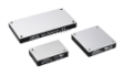
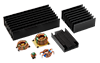
Half-brick Heat Sink:
The CHB200W12-72S series offers different Heat Sinks for users based on their different application conditions.

Fig. 15

Fig. 16
Conclusion:
Cincon Electronics has accumulated many years of professional experience in integrating power converters into the railway applications. We have rolled out the ultra-wide input range of CHB200W12-27S series with the input and output filter combination. In addition, they are compliant to the related railway standards such as EN 50155 and EN 50121-3-2. In addition to products themselves, their peripheral circuits have the full protections. Plus, there are a wide variety of cooling ways by the multiple Heat Sink choices. Their highly integrated features, for users, are cost-effective and greatly reduce the development phase.
Check more product info: CHB200W12
If you are interested in 150W, refer to CHB150W12.
Contact for more support: sales@cincon.com.tw