News & Events
The Ground Rules to Select and Build a Modular DC/DC Power System-IV: Load consideration
08
Apr
Apr 8, 2022
Premises recap:
In the earlier discussions, we talked about fundamental concepts, EMI solutions, and safety protection considerations for building a DC-DC power system. Those discussions mainly focus on the front-end DC-DC converter design. In the back-end, different types of load applications would affect the circuitry design to meet the requirement. In this article, we will discuss different types of load and the concept to build the circuitry.
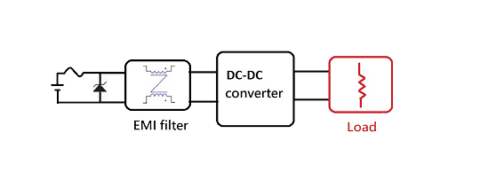
Fig 1. DC-DC modular system concept
1.Load introduction and output characteristic
Generally, a load could be separated into three types: resistive load, capacitive load, and inductive load. From physical point of view, they could be differentiated by the phases of voltage and current. For resistive load, the voltage and current cross together with no phase angle. For capacitive load, the voltage leads current with certain angle phase. For inductive load, the voltage lags current instead.
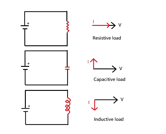
Fig2. Three types of loads
In practical application, you may see various loads mixed in a power system. However, it still could be distinguished a main type from those mixed loads. For instance, the resistive load could be referred to concrete load which is commonly used for burn-in testing or bleeder. For the inductive load, motor applications are commonly seen which draws an amount of current while starting up. For capacitive load, applications of battery charging are good examples and how to charge up to nominal voltage while start-up becomes a challenge.
2.Challenge for Inductive load and Capacitive load
The inductive load is mostly related to motor drive such as wheel robot or laundry machine in household application. Back to the electrical characteristic (Lenz’s law) of an inductor, the transient of current variance would cause the reverse voltage. In practical situation, while we switch on and off from the load side, the output voltage might drop to negative and damage the DC-DC converter in a short moment.
To protect the DC-DC converter from being damaged by reverse voltage, add a freewheel diode in parallel with the load to protect the DC-DC converter from reverse polarity voltage.
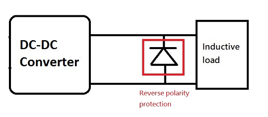
Fig 3. Connection circuitry for Inductive load
The capacitive load is commonly related to battery charging. From the capacitor charging and discharging equation, the output voltage needs time to reach to the nominal voltage or drop to zero. In practical application, the DC-DC converter might not be able to reach nominal voltage and fail at start-up. Also, there is a concern that the reverse current from output might damage the DC-DC converter.
To protect the DC-DC converter, add a diode in series connection would be a proper method to protect the DC-DC converter from the risk of possible damage.
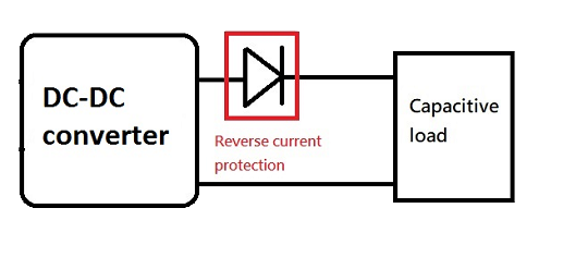
Fig 4. Connection circuitry for Capacitive load
3.Transient load and Pulse load
Transient load represents the scenario that heavy and light load switch quickly, showing the challenges the stability of the converter. Pulse load could be seen as a similar case to transient load, but it is seen as the periodic spike load. In both conditions, the DC-DC converter has to stand the stress of load variance and provide a stable output voltage.
To reduce the stress of the converter and provide stable output, paralleling a few capacitors at the output would mitigate the stress of the converter. However, beware not to exceed the capacitive load limitation of DC-DC converter.
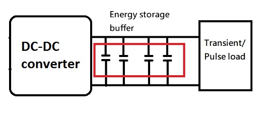
Fig 5. Connection circuitry for Transient/ Pulse load
4.Series and Parallel for increasing load wattage
Series connection and Parallel connection are two common methods to increase load wattage in the application. Series connection is simpler and doesn’t need to worry about the current sharing problem. However, the output voltage will be added up by the quantity of converters in series connection.
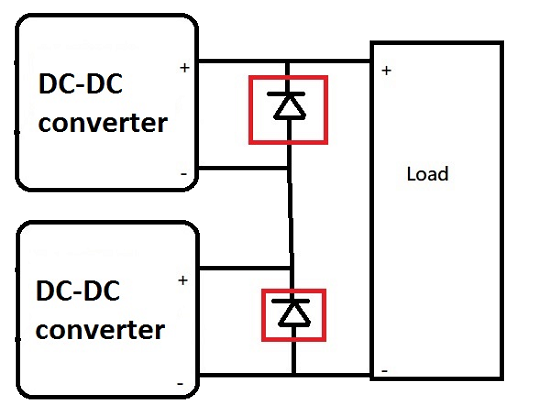
Fig 6. Connection circuitry for in-series application
Another common way is to parallel the units and get higher wattage. The advantage is that the output voltage stays the same and it is easier to increase the overall wattage by paralleling multiple DC-DC converters. However, due to the small impedance difference of each converter, current sharing would be unbalanced and possibly cause problems such as reducing the reliability of DC-DC converter, resulting in output failure due to the trigger of over-current protection, etc. There are two key points that need to be resolved:
a.Start-up
b.Current balance during operation
During the start-up moment, the whole set would not start up properly if one of the DC-DC converters in parallel connection triggers hiccup-mode OCP. There are two ways to avoid this situation: two-stage startup and constant current design. The two-stage startup is to turn on the set of DC-DC converters without taking load first and then connect to the load later. The constant current is a straightforward answer to avoid the unit shutdown during start-up.
If the current sharing is balanced properly during operation, the reliability of the set would be unstable due to the wattage stress on certain units.
Most common solutions to achieve the parallel connection:
a.Droop method
b.Active current sharing
The droop method is to add external resistors at the output of each converter. By applying this method, the higher current path would have larger voltage drop, which forces the current to flow to the other side.
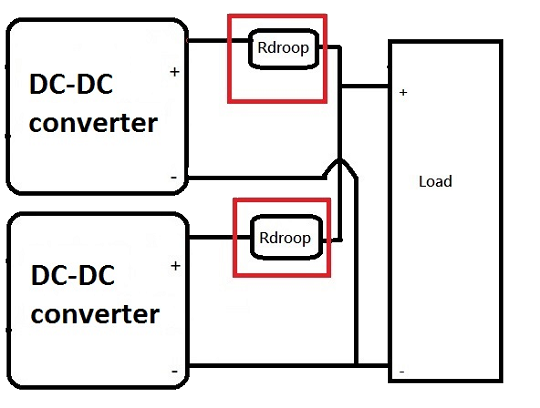
Fig 7. Droop method for Parallel connection
The active current sharing method uses communication pin (or called parallel pin) to balance the current between all modules by adjusting the voltage internally through feedback loop.
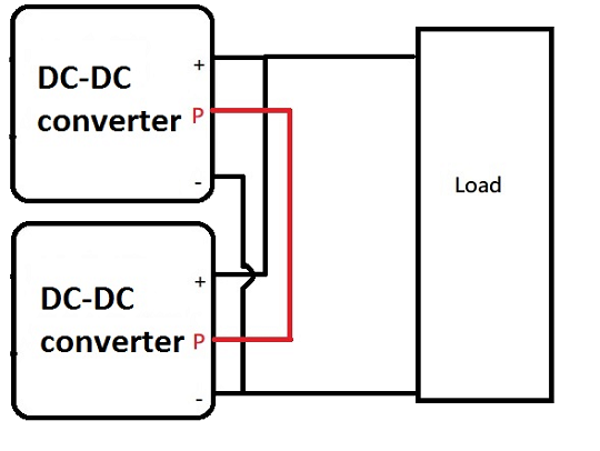
Fig 8. Active current sharing connection
5.N+1 redundancy for fault tolerance
The concept of redundancy is to ensure the system would keep running when failure of power module happens. To achieve this feature, two of the power modules would be connected parallelly but only draws a single power wattage rating. A diode should be added at the output side of each module in case of the output voltage is pulled down when failure happens.
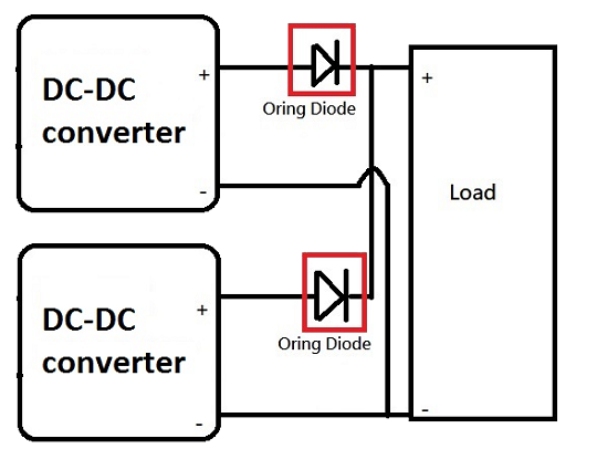
Fig 9. Redundancy connection circuitry
Summary:
In this article, we discuss various types of loads and the concepts corresponding to the applications. Due to the advantage of the compact size, the DC-DC converter could be utilized with much more flexibility. For further detailed information, please check our application notes or contact us for your questions.
Contact for more support: sales@cincon.com.tw
More articles:
The Ground Rules to Select and Build a Modular DC/DC Power System-I
The Ground Rules to Select and Build a Modular DC/DC Power System-II
The Ground Rules to Select and Build a Modular DC/DC Power System-III


